Why My Robot Doesn't Behave as Expected: Sensor Noise, Encoder Quantization, and PID Tuning
Why My Robot Doesn't Behave as Expected: Sensor Noise, Encoder Quantization, and PID Tuning
Category: Robotics · Embedded Systems · Control Systems
A robot can have a well-designed PCB, a powerful microcontroller, and a carefully implemented control algorithm, yet still fail to move as expected.
It might turn slightly more than intended, struggle to maintain a constant velocity, oscillate while following a path, or produce inconsistent results even when running the same code.
When developing mobile robots, I learned that these problems are not always caused by incorrect PID gains. Sometimes, the real challenge is obtaining reliable measurements from the hardware itself.
Motor characteristics, sensor noise, encoder resolution, and timing all influence how a control system behaves in practice.
In this article, I explore some of the challenges involved in getting a robot to behave predictably, particularly when working with rotary encoders and closed-loop motor control.
1. Missing Encoder Ticks: When the Measurements Don't Match Reality
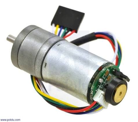
Rotary encoders are essential for estimating motor speed and measuring wheel movement. By counting encoder transitions over time, a microcontroller can estimate how far a wheel has rotated and how fast the motor is running.
However, the measured count does not always match the number of transitions generated by the encoder.
This is particularly noticeable when using interrupt-based encoder reading on a microcontroller.
For example, suppose an encoder should produce 1000 count events during a particular movement, but the firmware records only 930. The missing counts introduce an error into the estimated position and velocity.
There are several possible reasons for this:
Missed interrupts: Encoder edges arrive faster than the firmware can process them, especially when interrupts are disabled for too long.
Incorrect interrupt configuration: The firmware may detect only rising edges when the calculation assumes both rising and falling edges.
Electrical noise: Noisy signals can create false transitions or interfere with valid encoder edges.
Signal integrity problems: Long wires, poor grounding, and unsuitable pull-ups for open-collector outputs can affect signal quality.
Incorrect count calculations: Confusing pulses per revolution with counts per revolution can introduce a consistent scaling error.
The important point is that a low encoder count does not automatically mean the encoder itself is faulty. The problem may originate in the electrical interface, interrupt configuration, or counting method.
How I would investigate missing ticks
My first step would be to compare the expected encoder count with the measured count at different motor speeds.
If the counts match at low speeds but begin to fall behind at higher speeds, that suggests a possible limitation in signal capture or interrupt handling.
I would then inspect the encoder signals with an oscilloscope or logic analyzer, verify the interrupt configuration, and check whether the selected counting method matches the encoder's specification.
For higher-speed applications, hardware encoder interfaces or timer-based quadrature decoding can reduce the software overhead associated with processing every transition in an interrupt routine.
Reliable velocity control begins with reliable encoder measurements.
2. Encoder Quantization Noise: Why Low-Speed Measurements Jump Around
One of the most interesting challenges in encoder-based control is quantization.
An encoder does not measure continuous motion. It reports discrete transitions. The microcontroller therefore estimates movement and speed from integer counts rather than directly observing a perfectly continuous value.
Consider a simple example in which a controller measures encoder counts over a fixed time interval.
If the measured counts change from 4 to 5, the estimated speed changes by 25%, even though the actual motor speed may have changed very little.
This is particularly noticeable at low speeds, when only a small number of encoder counts arrive during each sampling interval.
The resulting variation in the calculated speed is commonly described as encoder quantization noise.
Why this affects PID control
Suppose a controller uses the measured wheel speed as feedback.
The actual motor speed may be relatively stable, but the estimated speed fluctuates because the encoder produces only a few count events during each measurement window.
The PID controller sees these fluctuations as changes in speed and reacts to them.
Depending on the controller settings, this can lead to:
Unnecessary PWM adjustments.
Small oscillations in motor speed.
Noisy derivative terms.
Uneven low-speed movement.
Difficulty maintaining a smooth velocity profile.
Increasing the PID gains does not solve the underlying measurement limitation. In some cases, it makes the system more sensitive to the noisy feedback.
Improving low-speed velocity estimation
There are several ways to address this problem.
1. Increase the measurement window
Counting pulses over a longer interval gives a better average estimate of speed, particularly at low RPM. However, it also introduces more delay into the control loop.
2. Measure the time between encoder edges
Instead of counting pulses during a fixed interval, the controller measures the time between successive transitions.
This can improve low-speed resolution, although the estimate becomes stale when pulses stop arriving and may be affected by timing jitter.
3. Apply suitable filtering
A moving average or low-pass filter can reduce fluctuations in the estimated speed. The filter must be selected carefully because excessive filtering adds delay and can weaken control performance.
4. Use an encoder with higher resolution
A higher-resolution encoder produces more count events for the same wheel movement, improving measurement resolution. However, it also increases the rate at which the microcontroller must capture transitions.
There is no universally best method. The right approach depends on encoder resolution, motor speed, sampling frequency, and the response required from the robot.
3. Understanding the Difference Between Encoder Resolution and Accuracy
Encoder resolution is another factor that can be misunderstood when designing a robot.
Resolution describes the smallest change in position represented by the encoder's output. Accuracy describes how closely the measured position corresponds to the actual position.
A higher-resolution encoder can provide finer position measurements, but it does not automatically guarantee accurate measurements.
Mechanical backlash, wheel slip, mounting errors, missed transitions, and incorrect conversion factors can still introduce significant errors.
For example, when calculating wheel displacement, the controller must account for the effective wheel circumference and the encoder counts per wheel revolution.
A simplified relationship is:
[
d = \frac{N}{C}\pi D
]
where:
(d) is the estimated wheel displacement.
(N) is the measured encoder count change.
(C) is the effective encoder counts per wheel revolution.
(D) is the wheel diameter.
The value of (C) must match the actual counting convention used by the firmware, including any quadrature decoding multiplication and gearbox effects.
If the encoder is mounted on the motor shaft, the gearbox ratio must also be included when converting motor rotation into wheel movement.
Even a small error in these parameters can accumulate over a long movement.
4. PID Tuning Cannot Fix Every Hardware Problem
PID control is widely used to regulate motor speed and position. It adjusts the control output according to the difference between the target value and the measured value.
where (e(t)) is the error between the target and measured values, and (K_p), (K_i), and (K_d) are the proportional, integral, and derivative gains.
Each term has a different role.
Proportional: Responds to the current error.
Integral: Accumulates error over time.
Derivative: Responds to how quickly the error changes.
Increasing the proportional gain can make a motor respond more strongly to errors, but excessive gain can cause oscillation.
Integral action can help eliminate steady-state error, but excessive integral gain can lead to overshoot and integral windup.
Derivative action can improve damping in some systems, but it is particularly sensitive to noisy measurements.
Why a robot can still behave badly
A common mistake is to keep adjusting PID gains when the actual problem lies elsewhere.
For example, a motor may not move at low PWM values because the available torque is insufficient to overcome friction. The controller may continue increasing its output until the motor finally starts moving, producing a sudden jump.
Similarly, a controller cannot compensate reliably for encoder counts that are consistently being lost.
Before tuning the controller, I would check the motor response, encoder readings, sampling interval, and PWM output. Only after confirming that the feedback measurements are trustworthy would I focus on tuning the PID gains.
A control algorithm is only as useful as the measurements and hardware it depends on.
5. Motor Dead Zones, Friction, and Unequal Wheels
Even two nominally identical motors may not behave exactly the same.
Differences in winding resistance, gearbox friction, wheel alignment, load, and manufacturing tolerances can cause one wheel to rotate faster than the other under the same PWM command.
At low PWM values, a motor may not move at all. Once the PWM crosses a certain threshold, it may start rotating abruptly.
This creates a nonlinear relationship between PWM and motor speed.
For a differential-drive robot, these differences can cause the robot to drift even when both motors receive identical commands.
A practical solution is to measure each motor's response and characterize its usable operating range.
Depending on the application, the controller may use a minimum effective PWM, a calibrated feedforward term, or separate control parameters for the left and right motors.
However, a minimum PWM should not be applied blindly. It must be compatible with the desired speed, motor characteristics, and control strategy.
Encoder feedback helps compensate for differences between the motors, provided the encoder measurements are reliable.
6. Sampling Time Matters More Than It First Appears
A feedback controller repeatedly measures the system, calculates an error, and updates the control output.
The time between these updates affects how well the controller responds to changes.
If the sampling interval varies significantly, the measured velocity and the PID calculations may become inconsistent.
This is especially important when the firmware performs several tasks, such as reading multiple sensors, communicating over a bus, updating a display, and processing encoder events.
For a velocity controller, I would aim for a consistent control-loop interval and use the actual elapsed time when calculating speed and time-dependent PID terms.
For example, the measured velocity over a sampling interval can be calculated as:
[
v=\frac{\Delta N}{C}\frac{\pi D}{\Delta t}
]
where (\Delta N) is the change in encoder count and (\Delta t) is the elapsed time.
This equation makes it clear that errors in the count difference or sampling time directly affect the velocity estimate.
Keeping the control loop predictable makes it easier to interpret measurements, tune the controller, and reproduce experimental results.
7. A Practical Debugging Workflow
When a robot does not move as expected, I would avoid changing several parameters simultaneously. Instead, I would investigate the system in stages.
Step 1 — Check the hardware
Verify the motor supply, driver connections, encoder wiring, and ground connections.
Step 2 — Verify encoder counts
Rotate the wheel by a known amount and compare the measured count with the expected count. Repeat at different speeds.
Step 3 — Test open-loop motor control
Apply controlled PWM commands without closing the velocity loop. Record the motor's response and identify its approximate dead zone.
Step 4 — Calculate velocity
Use encoder count changes and a known sampling interval to calculate wheel speed. Check whether the measurements are sufficiently stable for the intended controller.
Step 5 — Tune the controller
Begin with proportional control, then introduce integral and derivative action only as needed. Monitor the response rather than relying on trial and error alone.
Step 6 — Test under realistic conditions
Repeat the tests with the robot on the actual surface and under its normal load. Wheel slip, battery voltage, and mechanical friction can change the results.
This process helps separate electrical faults, measurement limitations, mechanical effects, and control problems instead of treating every symptom as a PID issue.
Final Thoughts
Developing a reliable robot requires more than implementing a control algorithm. It requires understanding the entire feedback loop, from the physical motor and encoder to the measurement process and the controller.
Missing encoder ticks can lead to incorrect position and speed estimates. Quantization noise can make low-speed feedback fluctuate even when the motor is moving relatively smoothly. Motor dead zones, mechanical differences, and inconsistent sampling can introduce further challenges.
These problems are closely connected, which is why debugging them systematically is so important.
My main takeaway is that before tuning a controller to make a robot behave better, make sure the robot is measuring its own movement correctly.
Reliable measurements provide the foundation for reliable control.