Designing a Battery-Powered Embedded Device: Charging, Protection, Power-Path Management, and Fuel Gauging
Designing a Battery-Powered Embedded Device: Charging, Protection, Power-Path Management, and Fuel Gauging
Category: Embedded Systems · Power Electronics · PCB Design
Designing a battery-powered embedded device involves much more than connecting a battery to a voltage regulator. The battery must be charged safely, protected against abnormal conditions, monitored accurately, and integrated properly with the rest of the electronics.
These requirements become particularly important in compact devices that use microcontrollers, displays, sensors, wireless communication, and other peripherals. A poorly designed power system can cause unexpected resets, inaccurate battery readings, charging problems, or even permanent battery damage.
While working on embedded hardware, I started looking more closely at how battery charging, protection, power-path management, and fuel gauging work together. In this article, I'll explain these concepts and discuss the main considerations when designing a custom PCB for a battery-powered device.
1. Understanding the Battery Power System
A typical battery-powered embedded device includes a charging input, a battery charger, a battery protection circuit, voltage regulators, and the electronic load. A fuel gauge may also be included when the device needs to display its remaining battery capacity.
Each component has a different responsibility.
The charger controls how the battery is charged. The protection circuit helps prevent specified electrical faults. The voltage regulator provides the voltage required by the electronics. The fuel gauge estimates the remaining battery capacity, while power-path management controls how power is shared between an external supply, the battery, and the system load.
Some integrated circuits combine multiple functions, but these functions should still be considered separately during the design process.
2. Understanding the BMS and Battery Protection
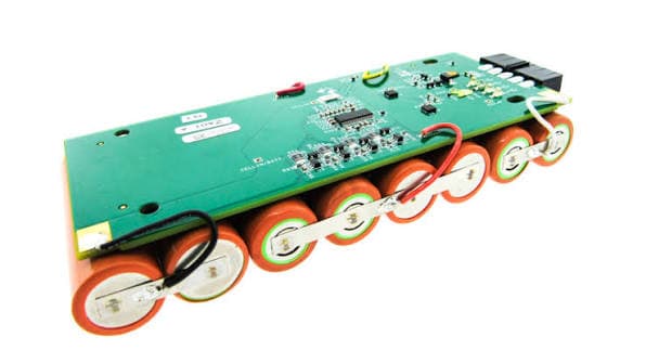
A Battery Management System (BMS) is used to monitor and manage a battery pack. In small embedded devices, the term BMS is sometimes used to describe a basic battery protection circuit, but a complete BMS can provide additional features.
Common battery protection functions include:
Overcharge protection to prevent the cell voltage from exceeding its permitted limit.
Over-discharge protection to disconnect the battery when its voltage becomes too low.
Overcurrent protection to respond when the current exceeds a specified limit.
Short-circuit protection to respond to dangerously high current.
Temperature protection to prevent charging or discharging outside the permitted temperature range.
Not every protection circuit includes all these functions. More advanced battery management systems may also monitor individual cells, estimate battery condition, and balance cells in a multi-cell pack.
A common example of a simple single-cell protection circuit uses a DW01A protection IC with MOSFETs. The IC monitors specified electrical conditions and controls the MOSFETs to interrupt the current path when a supported fault is detected.
However, a basic protection circuit does not necessarily provide accurate battery percentage information, temperature monitoring, or cell balancing.
Single-cell and multi-cell batteries
Battery configuration is an important factor when selecting protection and charging components.
A conventional single-cell lithium-ion battery, known as a 1S battery, typically has a nominal voltage of 3.6–3.7 V and a maximum charging voltage of 4.2 V.
A conventional 2S lithium-ion pack has a nominal voltage of 7.2–7.4 V and a maximum charging voltage of 8.4 V. A conventional 3S pack has a nominal voltage of 10.8–11.1 V and a maximum charging voltage of 12.6 V.
These values apply to conventional lithium-ion cells with a 4.2 V maximum charging voltage per cell. Other battery chemistries have different voltage limits.
For multi-cell batteries, protection must account for individual cell voltages, not just the total pack voltage. A protection circuit designed for a single cell must not be assumed suitable for a 2S or 3S battery.
3. How Lithium-Ion Battery Charging Works
Lithium-ion batteries require controlled charging. A charger must regulate the charging current and voltage according to the battery manufacturer's specifications.
Charging generally involves three stages.
Preconditioning: If the battery voltage is very low, a compatible charger may apply a reduced current to bring the cell into its normal charging range. Some chargers disable charging if the cell is too deeply discharged.
Constant-current charging: The charger supplies a controlled current while the battery voltage gradually increases. The selected current must be suitable for the battery and the available input supply.
Constant-voltage charging: The charger maintains the specified maximum cell voltage while the charging current gradually decreases. Charging terminates according to the charger's configured criteria.
For a conventional 4.2 V lithium-ion cell, the constant-voltage stage is normally regulated to 4.2 V. The correct charging current depends on the battery's specifications, so a charger capable of delivering 1 A does not mean every battery can safely accept that current.
A 2S lithium-ion battery requires a charger designed for a two-cell pack, typically providing an 8.4 V charging voltage. The circuit must also provide appropriate protection for both cells.
For example, the MCP73831 is a single-cell charger. It cannot directly charge a conventional 2S battery.
4. Charging Without Power-Path Management
In a simple battery-powered design, the charger charges the battery while the device draws power from the battery terminals.
When an external USB supply is connected, the charger must provide current for battery charging while the system continues operating. The battery and the device therefore share the available current at the battery node.
If the device consumes a significant amount of current, less current may remain available for charging. In some situations, the battery may charge very slowly or continue discharging while the external supply is connected.
The system load can also interfere with the charger's charge-termination behavior, depending on the circuit and the charger's operating method.
The main advantages of this approach are its low component count, simple implementation, and relatively low cost. It can be suitable for basic devices with modest loads and straightforward charging requirements.
However, it may be less suitable for products that must operate continuously while charging, especially when the load current changes significantly.
The MCP73831 is an example of a charger that does not include integrated power-path management. If it is used in a design that operates while charging, the interaction between the load and the charging circuit must be considered carefully.
5. Charging With Power-Path Management
Power-path management provides better control over the relationship between the external power supply, the battery, and the system load.
When USB power is available, a suitable power-path circuit can supply the system from the external input while managing battery charging separately. Depending on the design, the battery can supplement the input supply when the system requires more current than the input can provide.
When USB power is removed, the battery can take over powering the system, provided the circuit and battery support the required operating conditions.
The main benefits include more predictable charging behavior, better management of limited input current, and smoother transitions between external and battery power.
Power-path management is especially useful in devices that need to remain operational while connected to a charger.
However, it adds design considerations involving input current limits, system voltage, thermal performance, and battery compatibility.
MCP73831 versus BQ24074
The MCP73831 is a basic single-cell lithium-ion charger without integrated power-path management.
The BQ24074 is a single-cell charger with integrated power-path management. It is designed to manage the external input, battery charging, and system power more effectively.
Both devices are intended for single-cell charging applications. Neither should be used to charge a conventional 2S battery directly.
For a compact single-cell device that needs to operate while charging, the BQ24074 may simplify the design. For a simpler product, the MCP73831 may be sufficient if its limitations are acceptable.
It is important to remember that power-path management does not automatically replace battery protection. The complete design must still provide the protection functions required by the battery.
6. What Is a Fuel Gauge?
A fuel gauge estimates how much usable battery capacity remains. It serves a different purpose from the charger and protection circuit.
Battery voltage alone is not always a reliable indicator of state of charge. Voltage changes with load current, temperature, battery chemistry, and internal resistance.
For example, the voltage of a battery may temporarily drop when a motor starts and recover when the motor stops. A system that estimates battery percentage using only voltage thresholds may therefore display inaccurate or unstable readings.
A dedicated fuel gauge uses battery-related measurements and an estimation algorithm to provide a more useful estimate of remaining capacity.
Two important battery terms are state of charge and state of health.
State of charge (SoC) estimates how much capacity remains relative to the usable capacity of the battery.
State of health (SoH) describes how the battery's current condition compares with its expected condition when new.
A fuel gauge may provide state-of-charge information without offering a complete state-of-health estimate. Its capabilities depend on the selected IC.
Example: MAX17048
The MAX17048 is a fuel-gauge IC designed for single-cell lithium-ion batteries. It estimates state of charge using Maxim's ModelGauge algorithm and communicates with a microcontroller over I2C.
The microcontroller can read the estimated battery percentage and voltage, display the battery level on a screen, generate low-battery warnings, or initiate a controlled shutdown.
The MAX17048 does not replace the battery charger or protection circuit. It is also important to choose a gauge that supports the battery configuration being used.
For embedded devices with displays, a fuel gauge can provide a better user experience than estimating the battery percentage using voltage thresholds alone.
7. Battery Protection, Charging, and Monitoring Are Different Functions
These functions are often confused during schematic design, but each addresses a different requirement.
The battery charger controls charging voltage and current. The protection circuit responds to specified electrical faults. The power-path manager controls how the input supply, battery, and system load interact. The fuel gauge estimates remaining capacity, while the voltage regulator provides the required operating voltage to the electronics.
Some ICs integrate multiple functions, but it is still important to verify that every required function is supported.
For example, a charger may regulate the battery voltage correctly while still requiring a separate protection circuit. Similarly, a fuel gauge may report that the battery is nearly empty but may not have the ability to disconnect it.
A reliable design evaluates these requirements individually instead of assuming that one IC handles everything.
8. Selecting the Correct Voltage Regulator
Battery voltage changes during charging and discharging, while most electronic components require a stable operating voltage.
A conventional single-cell lithium-ion battery can reach 4.2 V when fully charged and fall to a lower voltage as it discharges. The exact operating range depends on the cell and the system's cutoff requirements.
The regulator must support the complete intended battery voltage range.
A buck converter reduces a higher input voltage to a lower output voltage. A boost converter increases a lower input voltage. A buck-boost converter can regulate the output when the input moves above and below the required output voltage. An LDO regulator provides linear regulation when its voltage-drop, current, and thermal limitations are acceptable.
The correct choice depends on the battery voltage, load current, efficiency requirements, noise sensitivity, and available PCB area.
Estimating power consumption
Suppose a device requires a 3.3 V supply at 300 mA. Its output power is approximately 0.99 W.
If the regulator operates at 90% efficiency, the required input power is approximately 1.1 W. At a battery voltage of 3.7 V, the battery current would be approximately 297 mA under these illustrative steady-state conditions.
Actual current varies with battery voltage, regulator efficiency, and load behavior.
When designing a real device, average current is not the only important value. Peak currents from wireless communication, displays, motors, buzzers, and other peripherals must also be considered.
A regulator that works under average load conditions may still fail when the device experiences short current peaks.
9. USB-C, Thermal Design, and PCB Protection
USB-C is a convenient charging interface, but using a USB-C connector does not automatically allow a circuit to draw any desired current.
For a basic USB-C sink using a 5 V input, the appropriate configuration-channel resistors must be included according to the USB-C specification. Higher power levels may require additional USB-C or USB Power Delivery functionality.
The design should also consider input overvoltage protection, transient protection, connector pin assignments, reverse-current behavior, input current limits, and suitable decoupling capacitors.
Thermal design is particularly important when using a linear battery charger.
During constant-current charging, the charger's approximate power dissipation can be estimated by multiplying the voltage difference between its input and the battery by the charging current.
For example, a 5 V input charging a battery at 3.7 V with a current of 500 mA results in approximately 0.65 W of charger power dissipation under the simplified calculation.
This can produce significant heat on a small PCB. Actual thermal performance depends on the IC package, copper area, ambient temperature, and PCB layout.
The PCB must be designed to handle both the required current and the heat generated during charging. A correct schematic alone does not guarantee a reliable power system.
10. My Battery-Powered Design Checklist
Before finalizing a battery-powered embedded device, I would check the following:
Confirm the battery chemistry, cell count, capacity, and permitted charging current.
Select a charger that supports the exact battery configuration.
Decide whether power-path management is required.
Provide appropriate battery protection and any required temperature monitoring.
Choose a compatible fuel gauge if battery-state reporting is needed.
Select regulators that operate across the full battery voltage range.
Calculate average and peak load currents.
Verify the USB-C input configuration and protection.
Check charger thermal performance at the maximum expected charging current.
Add test points for the battery, input supply, system rail, and relevant control signals.
Test charging, discharging, and transitions between USB and battery power before relying on the final design.
Final Thoughts
Designing a battery-powered embedded device requires careful coordination between several parts of the power system.
The charger controls the charging process, the protection circuit responds to specified battery faults, the power-path manager handles the relationship between the input supply and system load, and the fuel gauge estimates remaining battery capacity. Voltage regulators then provide suitable power to the electronics.
Understanding these differences makes it easier to select the right components and avoid common mistakes during schematic design.
For me, the key lesson is that battery management should be considered part of the overall system architecture from the beginning. Battery configuration, charging behavior, peak load current, thermal performance, protection, and monitoring all influence the final circuit.
A good battery-powered design does more than charge a battery. It manages energy safely, supplies the electronics reliably, and gives the system a useful understanding of the battery's condition.